|
|
PCM-X1 Processor The purpose of the PCM-X1 is to develop a device to convert PCM audio into a pseudo video signal suitable for recording onto video tape. This will allow any VCR to act as a DAT recorder. My goal is to build a PCM processor that can connect to any PAL video recorder with at least 240 lines of horizontal resolution. The proposed specifications are as follows:
The beauty of such a system is the fact that one will be able to record up to the limit of a standard VHS E-240 cassette, which is 4 hours of stereo PCM sound! The first step would be to get my hands on the actual 16-bit samples so that I can read them into a buffer, and clock them out at the video line rate. To this end I have built a DAC-ADC board to experiment with:
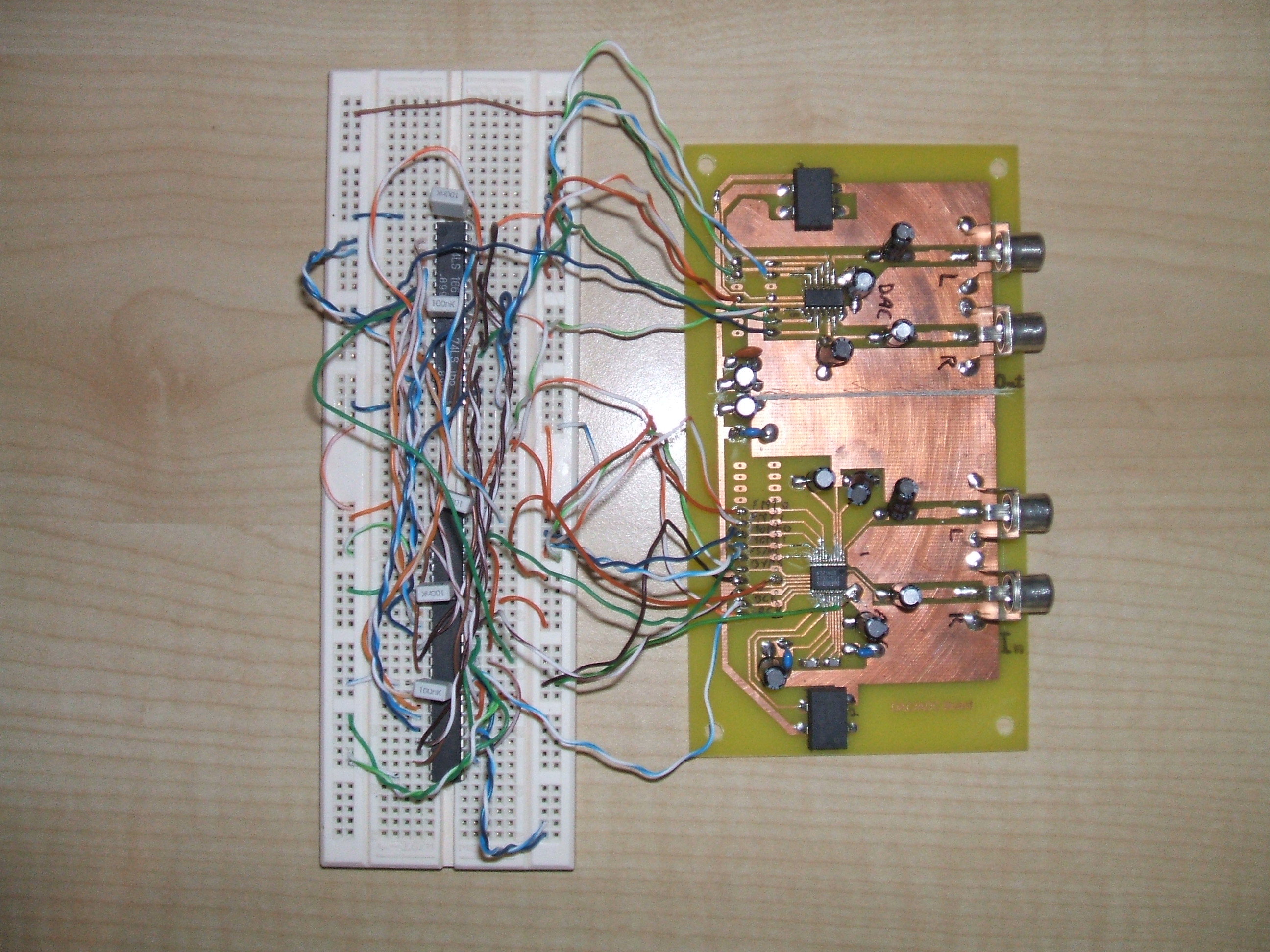
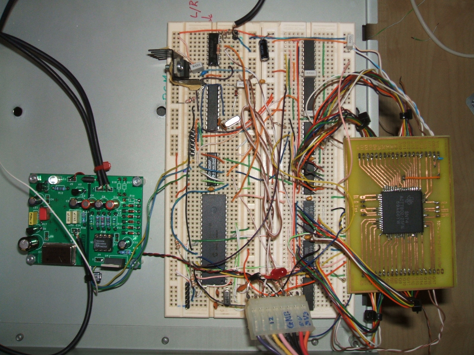
The serial-parallel-serial converter with ADC/DAC (left) and PIC16F690 based video sync generator (right) circa December 2006 The DAC ADC board uses a PCM1800 ADC and a PCM1725 DAC. Both are samples kindly provided by Burr-Brown. This board layout was my first attempt. I have learnt much in the meantime about ground planes and so on. Both chips process PCM samples in serial format. The chips on the left are 74LS166 x 2, 74HC595 x 2 and a 74HCT14. Their purpose is to convert the serial PCM data stream from the ADC to a parallel data stream, and back to serial for the DAC. I did it like this because then I can place an 18bit FIFO buffer in-between. This setup worked well.
For the PCM-X1 I'll require an interface to a CD player as a source of PCM audio. I have ordered a DAC board with SPDIF interface from DIYparadise. This board contains an SPDIF interface chip called the CS8414 that will give me PCM audio samples from a CD player. This serial PCM data stream can then be converted to a parallel data stream, stored in the FIFO buffer and read out at video line rates as a pseudo video signal. I'm also looking into using a PIC24, 40MIPS 16-bit MCU from microchip to act as a FIFO buffer using its' onboard RAM. By doing this I can add features like interleaving and error correction/detection in software. This is for much later though.
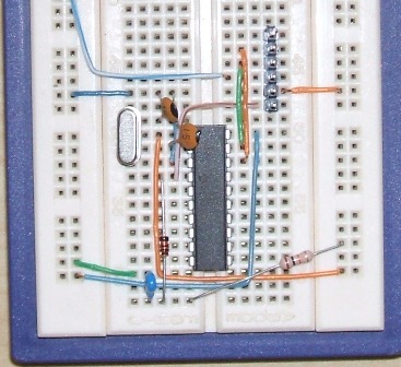
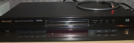
My signal source is a Sherwood CD player. The light beam from the TOSLINK cable can be seen clearly.
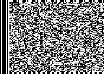
In the end of the day, what I'm looking to accomplish is something like this:
PCM data encoded into a video frame that can be recorded onto video tape. The above picture is from a site that describes the Backer 32 for Linux. Backer 32 was a card made by the now defunct Danmere company. It allowed you to backup computer data to video tape. It occurred to me that I never included the calculations I made to figure out how many samples per line I need to record. Here goes: The bit rate of the incoming PCM audio is 44100 x 16 x 2 = 1411200 bits per second. This means I have to record 1411200 bits in one second. Now we know one PAL video field lasts 1/50 second. This means that I have to record 1411200 / 50 = 28224 bits per field. One PAL field contains 312.5 lines, but the first and last few lines don't contain video. Through calculation I have found that if I select 294 of the 312.5 lines, I can fit exactly 96 bits one one line of video, 28224 / 294 = 96 That is equal to 6 x 16 bit samples per line for 294 lines per field. Other numbers of lines would produce fractions of samples at the end of a line. Something I want to avoid.
The active portion of the video line is 52 μs long. Recording the worst case scenario, using NRZ encoding, of 101010101010101010101010101010101010101010101010101010101010101010101010101010101010101010101010 in 52 μs produces maximum video frequencies of :
48 cycles (1 to 0) in 52 μs gives me a frequency of 923.076 kHz. This is only the fundamental frequency though. To reproduce the steep pulse edges required for timing accuracy the third harmonic must be present. This means a bandwidth of 923.076*3 kHz, or 2.7 MHz. Well within the video bandwidth of a typical VHS recorder (about 3MHz). When recording all zeros or all ones, there will be a large DC component. This is not a problem as video recorders can record DC ie. all white line or all black line.
26 August 2007
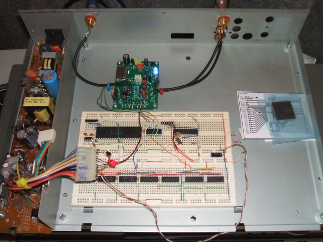
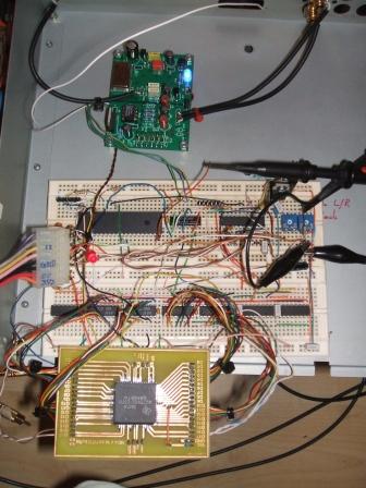
The PCM-X1 PCM Processor as it appears now. I'm using the chassis from an old satellite reciever. The "recycled" power supply is on the left. The SPDIF reciever and input monitoring DAC is on the little green board. This is the one I mentioned previously that I ordered from DIYparadise. The chips on the white breadboard are a PIC18F4550 that manages the FIFO buffer output and provides the unload clock. The PIC16F690 generates the composite PAL sync and indicates to the PIC18F4550 when it should unload data from the FIFO buffer. The chips below those are serial/parallel converters to interface the serial data stream from the SPDIF decoder to the FIFO buffer.
The FIFO buffer chip is in the little blue bag at the right. The host PCB is the one underneath the blue bag. I'll etch it an then put everything together. Then I should have the encoder part completed. Next, the decoder unit.
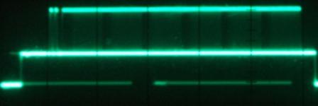
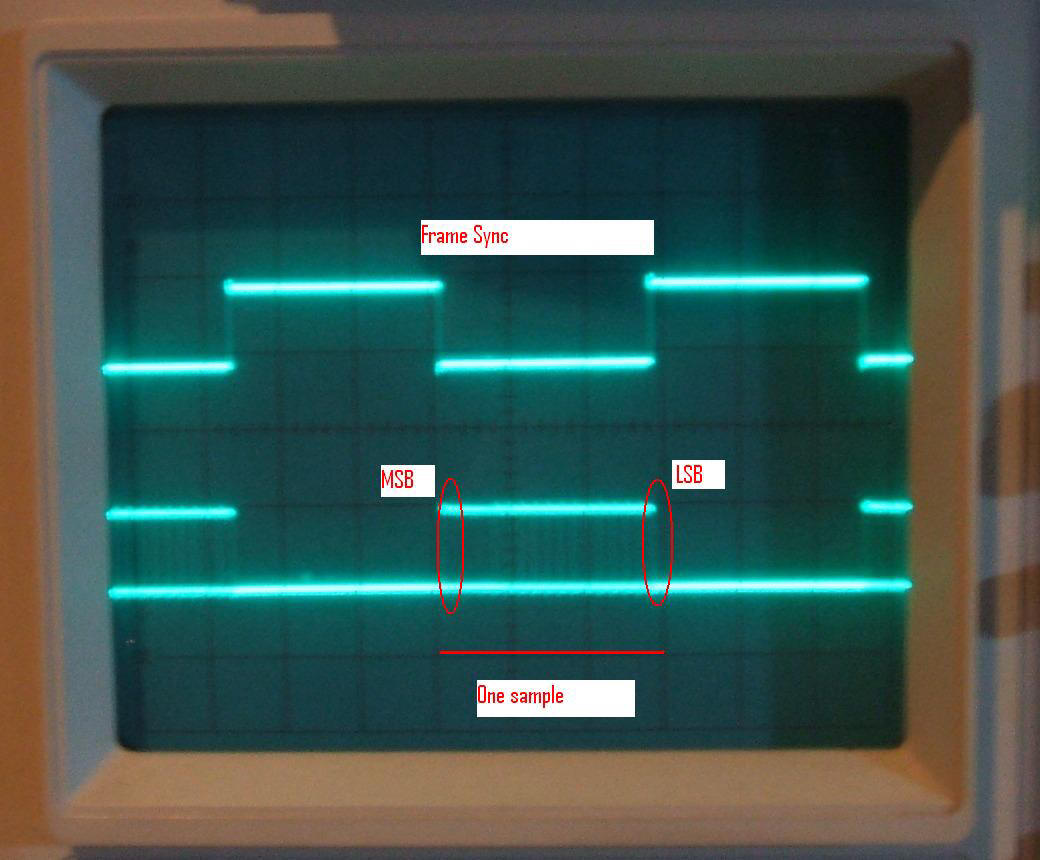
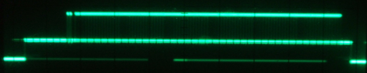
CS8414 SPDIF decoder chip output 1 September 2007 It works! After lots of planning, building and tweaking I have a working PCM encoder. The software for the PIC18F4550, that controls the FIFO output and parallel to serial converter, required quite a bit of tweaking to get everything to work reliably. Also, I discovered that the PAL sync generator was producing one line too many per field. I guess I need to learn how to count. Here's what it looks like now:
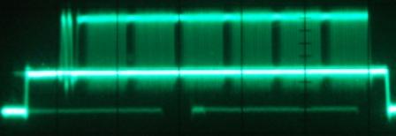
It's very hard getting a decent photo of the video signal output from the oscilloscope. The above picture shows about one and a half lines of video with their sync pulses. Each line contains six 16 bit samples clocked out one after another. In the top picture, the 1024x18bit FIFO buffer is the black square chip on the yellow and copper board. I still have to clean up the video line front porch area. 2 September 2007 Cleaned up the front porch of the video signal by tweaking my code to reset the 74LS166 (parallel-serial converter) earlier. I was using the composite sync before to reset the LS166. That's why the binary output stopped at the sync boundary before. Here is it now:
What looks like a colour burst before the data stream is actually a little sample of the clock. The reciever uses it as a valid line flag and also to sync it's internal clock. I'm calling this circuit the PCM-X1ep. PCM for Pulse Code-Modulation, X for experimental, 1 for working model one, e for encoder and p for parallel processing. The system as I have it now is rather complex. The input from the CS8414 is serial. I then convert to parallel for FIFO buffer storage and back to serial for output on the video signal. The parallel data lines, serial-parallel-serial converters and support circuits make the PCM-X1ep a finicky beast. I am having intermittent trouble with shift register lockups. The circuit ran flawlessly for seven hours yesterday! I hate intermittent faults. The next model will have simpler hardware and perform all functions in software using a dsPIC33. I have some learning to do till then. Up to now, I was doing all my coding in assembler.The dsPIC33 version will use the PICs onboard RAM for sample storage and will be programmed in C.
3 September 2007 I tweaked the DAC resistor network on the output stage and added an OR-gate to combine two data streams. I now have the video signal looking the way I want. Notice that the little clock runin pulse is cleaner and at the same level as the rest of the video. The large gap in front is where the colour burst would normally be. This area must be kept clear. PS. I'm getting better at taking photos off screen.
Click on pictures for bigger versions
The final PCM-X1. I'm going to leave it alone now and start working on the PCM-X2, which will do all the work in software using the PIC24.
Project Code Files Code for 18F4550 - Generates control signals for FIFO buffer and Serial-to-Parallel data conversion Code for 16F690 - Generates PAL composite sync and interrupt pulse to signal start of line for 18F4550
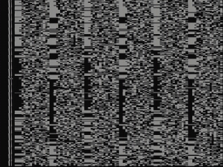
Here are some screen captures of the video output. This is what the VCR records and what you would see on a TV screen.
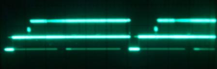
8 September 2007 Tried some test recordings after tweaking some more code. The VCR I'm using is a Philips VR730 Hi-Fi VHS recorder. It's appalling to see what VCRs do to video signals. It's amazing they produce viewable pictures at all! Here's the input signal to the VCR. Nice, clean square shapes
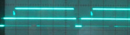
Here's the output signal once the VCR had a go at it.Yuck!
I guess it can be cleaned up. You're not interested in the amplitude variations after all
8 March 2008 I hauled out the VHS recordings I made of the output and captured 90 seconds to an AVI file. The sound you hear is the analog stereo sound from the VHS recorder. Download : pcm_processor_vhs_source.avi (56MB) Requires DivX (Removed 14/10/2008) Took up too much space on host. See my PCM-X2 instead.
Single field of PCM data
|
 Loud
Organ Music. Lots of low frequencies
Loud
Organ Music. Lots of low frequencies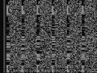 Normal
Pop music
Normal
Pop music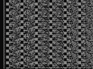 Steady
low frequency sinusoid
Steady
low frequency sinusoid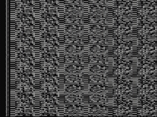 Steady
frequency sinusoid. Higher than previous
Steady
frequency sinusoid. Higher than previous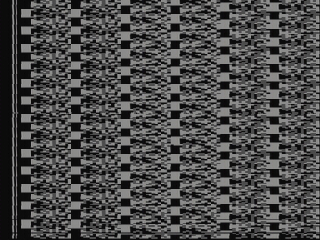 Steady
frequency sinusoid. Higher than previous
Steady
frequency sinusoid. Higher than previous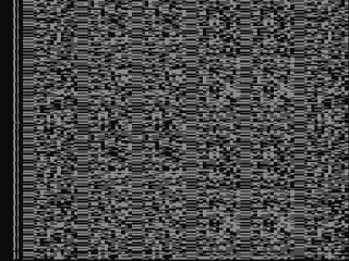 Steady high frequency sinusoid. Highest
 no
PCM data
no
PCM data