|
Hybrid components
2003 - 2009
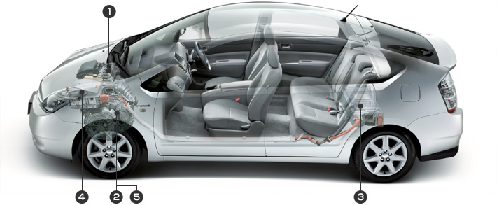
from toyota japan
-
1.5 litre VVT-i engine running on the Atkinson Cycle
-
Hybrid Transaxle
-
High
voltage NiMH battery pack
-
Power Inverter
-
Mechanical power-split device
1.5 Litre VVT-i engine Top
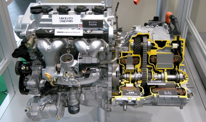
The 1NZ-FXE Engine
mated to the hybrid transaxle (right). The Prius engine uses the more efficient
Atkinson cycle.
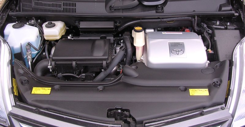
Everything neatly tucked away. The engine is on the
left underneath the
air filter. The inverter sits
on top of the hybrid transaxle on the right.
Hybrid Transaxle Top
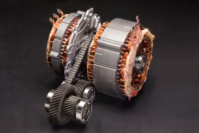
The Prius transaxle contain two electric motors that
can also act as generators (motor/generator or MG). The gears sticking out
in-between, couple the drive force to the wheels. The
power-split-device resides between
the two motors and together with the two motors create a type of continuously
variable transmission.
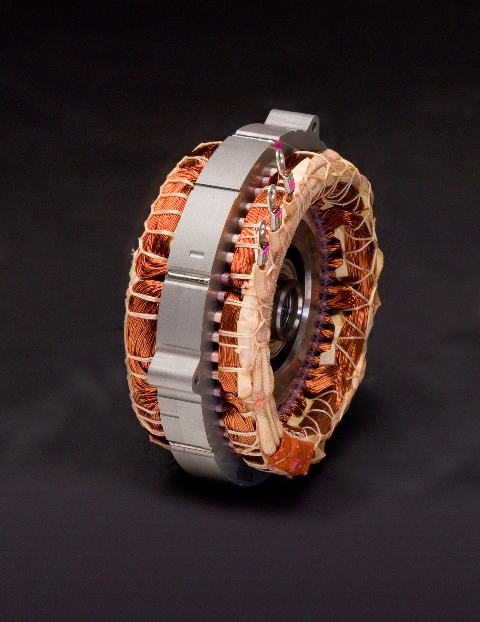
Motor/Generator 1 |
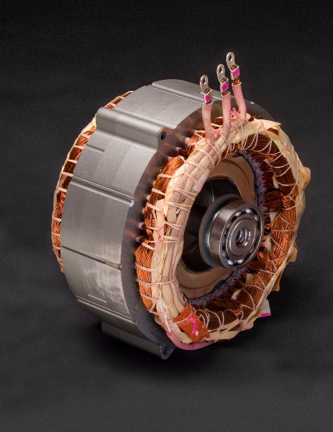
Motor/Generator 2 |
High
voltage NiMH battery pack
Top
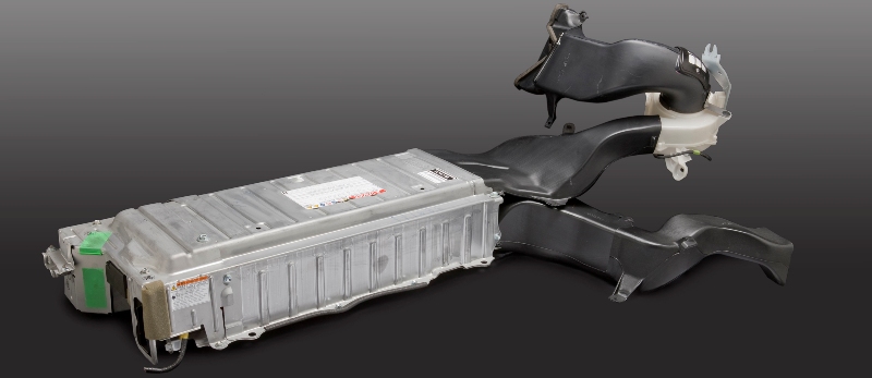
Prius HV battery with cooling ducts
Toyota uses prismatic NiMH modules from
Panasonic. Each module consists of six 1.2 V cells connected in series. The
module has a nominal voltage of 7.2 V, capacity of 6.5 Ah, weighs 1.04 kg, and
has dimensions of 19.6mm(W) x 106mm(H) x 275mm(L).
Further notable features are as follows:
- A thermal well on top of the cell allows measurement of an approximate
internal temperature of the electrolyte,
- A hydrogen vent provides for release of hydrogen through a manifold under
gassing conditions,
- Terminals on each side provide clean connections,
- Tie down bolts secure the modules to structural supports,
- A plastic case lowers mass, and
- The side surfaces of the module provide air gaps for airflow created by
dimples and protrusions when two modules are stacked. This Panasonic design has
improved in specific energy and power capabilities over the first generation
cylindrical cells that are in the 1997 - 1999 Japanese Prius
"Toyota says its out-of-warranty
battery replacement rate is 0.003 percent
—or one out of 40,000 Priuses—for
the second generation Prius"
First Numbers on Hybrid Battery Failure
"At 5 years and 106,500 miles,
mine is still going strong."
john1701a Senior Member Priuschat
The Pack
The Prius battery stack consists of 38 prismatic NiMH modules connected in
series. It delivers a nominal 273.6 Volts and has a 6.5 Ah capacity. The modules
are stacked side by side and then compressed together in a rigid, non-expandable
structure that prevents expansion from internal pressures. The complete battery
pack consists of the battery stack, enclosure for structural support and
airflow, battery electronic control unit/monitor, relays and safety switch. The
weight of the complete battery pack is 53.3 kg. The pack is horizontally
positioned in the boot of the vehicle partially under the back seat. Power
electronics (inverter, DC-AC converter) are under the bonnet and a blower for
moving air and associated air ducts are in the boot. Discharge power capability
of the Prius pack is around 20 kW at 50% SOC with regenerative capability of
14.5 kW at 2C. The power capability increases with higher temperatures and
decreases at lower temperatures. Active thermal management can improve power
capability at lower temperatures.
Battery Pack Thermal Management
The purpose of a battery thermal management system is to keep the batteries
operating within a desirable temperature range; prevent the batteries from
exceeding a high temperature limit that can damage the batteries and/or reduce
life; and maintain battery temperature variations to low levels to prevent
highly imbalanced batteries. Pack imbalances can reduce performance and can also
damage the battery and/or reduce life. Thermal management of the battery pack is
typically accomplished with the combination of two approaches. First, a
cooling/heating system is designed to extract/supply heat to the battery pack.
Second, the battery controller adjusts the vehicle’s use of the battery pack
based on the conditions in the batteries.
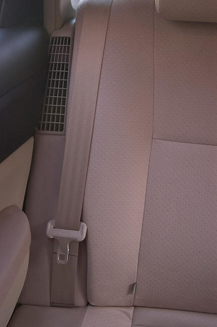
In the rear is a vent that draws cabin air in and over the
battery for temperature control. It is important not to block this vent.
Forced Air System
The Prius supplies conditioned air from the cabin as thermal management for
cooling the batteries. The pack’s forced air system consists of two vents
located in the cabin under the middle brake light (exhaust from the cabin or
inlet to the pack); ducting to the battery pack enclosure; the enclosure
manifold; air gaps between modules; ducting out of the pack to a blower that
pulls the air through the system; and two exhausts (one to the boot and the
other to the outside). A hydrogen vent from each module is connected in series
with tubing. Any gases released are exhausted from the vehicle through the gas
manifold to avoid any increased hydrogen concentration and, thus, potential for
explosion. Outside air is conditioned (heated or cooled) by the vehicle’s
thermal comfort system to a level comfortable for the driver. This approach has
the advantage of providing air that is not only comfortable to the passenger(s),
but also ideal for use in heating or cooling the NiMH batteries. However, the
Prius does not use the forced air for heating the batteries.
To achieve a
relatively uniform temperature distribution across the modules, a parallel
airflow scheme is used, rather than a series configuration. In a parallel
configuration, each module is set up to receive the same amount of airflow and
thus the same cooling. To achieve this in the Prius, cabin air enters the pack
through a plenum that runs beneath the battery stack horizontally from passenger
side to driver side. The cross-sectional area of the plenum is largest at its
entrance and linearly decreases as it goes under the modules. Then the air flows
vertically through the gaps between each module (formed from dimples and
protrusions on side walls). Finally, the air enters into the top plenum. This
plenum’s cross-section increases linearly in the direction of the flow. With
this design, the pressure drop across each module is expected to be uniform and,
consequently, should lead to a uniform flow rate around each module. The air is
drawn by a 12 V blower installed above the driver’s side rear tire well. The air
is either exhausted to the boot or through a vent on the driver’s side C-pillar.
The fan has four settings, depending on the maximum temperature of four
monitored batteries. Toyota also monitors the inlet and outlet air temperatures.
The fan settings are off, low, medium, and high speed. The blower setting
depended on temperature and transitions with hysteresis depending on whether
temperature is increasing or decreasing.
The Battery Pack Computer
The Prius has a computer that’s solely dedicated to keeping the Prius
battery at the optimum temperature and optimum charge level. Both these
functions maintain the long life of the battery. Toyota have lab data showing
the Prius battery can do 290,000km of normal driving with absolutely no
degradation of the battery’s performance. This long life is largely due to the
computers control of the Battery pack.
from
The clean green
car company
Battery System Diagnostics
In the event that a Prius has a HV battery that is too low for the car to be
started, Toyota dealers have a battery charging tool that allow them to charge
the HV battery from a standard AC outlet. Click on the image below for a pdf,
"High Voltage Battery Control Systems"
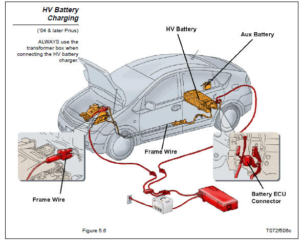
Battery charging system as used by dealerships to charge a
dead Prius battery
Power Inverter Top
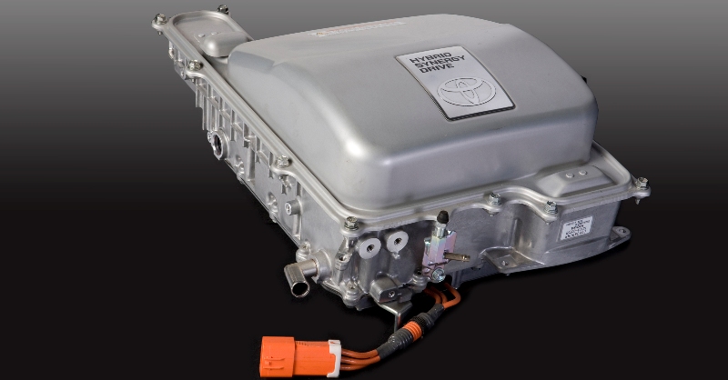
The
power inverter is an electronic
device that takes the high voltage DC from the battery and turns it into AC that
can drive the motor. The inverter also converts the AC power from the
motor/generators back into DC to charge the battery. The unit contains special transistors called
IGBTs that perform the power switching
functions. Inverter teardown
article located
here.
Mechanical power-split device Top
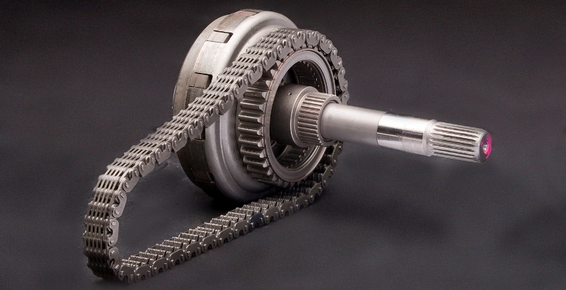
The Prius has no manual or automatic
gearbox in the normal sense. Instead it has a type of
CVT
or more accurately called a "power split device".
The PSD divides
power seamlessly between the engine, motor and generator in any ratio. Its'
operation is similar in some regards to a differential. The actual PSD is about
the size of a mans clenched fist. For a description of how it works, with
animation, click HERE.
|
